|
The
central headquarters of the Snowy Hydro LTD is located at Cooma. The many outlying
construction camps, field workers, medical and public
relations facilities required a comprehensive network
of automatic telephone exchanges, teleprinters, and
fixed and mobile radio networks to link all sections
of the Scheme.
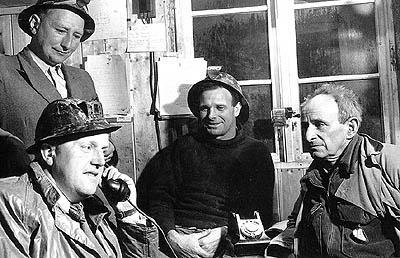
Tunnel engineers and geologists
using an old style telephone
(Raymond, 1999: 80) |
The
battery powered field telephones were used to return
important scientific data to base camps or to Snowy Hydro
in Cooma. They could also be used to relay weather forecasts,
notify accidents and call for assistance, and to warn
workers of impending gelignite blasts, above and below
ground.
A
network for the Snowy Mountains Scheme
The Snowy Mountains Scheme area is largely within the Kosciuszko National
Park. It was initially an undeveloped area with a few
dirt roads linking Cooma with Tumut, and to the Hotel
Kosciusko (sic) in 1949 when the constuction commenced. Thredbo,
Perisher, and Smiggin Holes were non-existent. The then
Post Master General's Department (PMG) — equivalent
to Telstra — operated both postal and telephone
services which were limited to a small capacity telephone
communication service for Cooma and old Jindabyne town.
The
SMA was operating over the total area of the National
Park. They were building camps, roads, tracks, and new
townships to enable the construction of dams, tunnels,
power stations, and construction power supplies such
as diesel power stations and transmission lines. Good
communications were vital. Being able to provide and
maintain the rapidly expanding communications service,
an agreement was reached between the PMG, and the SMA
permitting the Authority to establish its own network.
Mr F W Kelly, Communications Engineer, was charged with
the responsibility of developing this operation.
Kelly
purchased PABX exchanges from wherever he could, and
he set up small manual telephone exchanges in camps
and townships. A large telephone exchange in the Cooma
Head Office linked this into the PMG, and established
interconnecting cables and overhead lines. He also established
a radio telephone system which provided complete coverage
throughout the whole of the Snowy Scheme. Other services
(Kosciuszko National Park and Wild Life Service and
Police) sought access to the telephone service.
Most
likely, the Scheme would have taken much longer to complete
were it not for the excellent telecommunications system
installed, operated and maintained by F W Kelly and
his communications team during the construction era.
The
system was the equal of the established PMG system,
which served the capital cities at the time. Removal
of communication from construction sites and re-establishment
in new sites was commonplace. It was possible to telephone
locally, interstate, and overseas from the Authority
system.
|
Radio
Radio repeater stations were established at Kings
Cross (Cabramurra), Mt. Youngal above Geehi, and
Talbingo. At Youngal, a gas operated installation
provided electrical energy for radio equipment
prior to solar power being available. A mobile
radio system was established and motor vehicles
provided with radio transceivers, which gave an
excellent coverage for working parties in remote
areas.
Microwave
system
Eventually, a microwave system was established,
which is still the backbone of the communications
system of the Snowy Hydro. This microwave communications
and data transfer installation between Cooma Operations
Control Centre and the various power stations
throughout the regions provides remote control
and data acquisition facilities.
|
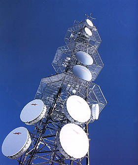
Photo of a digital microwave
system used on the Scheme (Raymond, 1999:
142) |
|
The
network is primarily based on digital technology where
the communications assets form a physical infrastructure
upon which the Snowy Hydro's operational and corporate
Communications users can have access to various communications
networks to meet voice and data communications needs.
The
physical network
Digital microwave radio network
The 7 GHz system incorporates space and frequency
diversity routes with duplicated microwave radio equipment
and segregated 8+8 Mb/s multiplex equipment. It forms
the backbone of the network. 2 GHz and
10 GHz systems are used as spur and minor links.
The
Power line carrier (PLC) network
The system consists of up to 6 channel analogue VF
links and 2 kHz teleprotection channels on the 330
and 132 kV transmission lines.
The
mobile radio network
The system consists of VHF high band radio equipment
incorporating 15 base stations linked between repeater
sites by microwave bearer. A number of repeater sites
are solar powered. (SMA, 1993: 163)
The Information transfer networks
Operation voice network
The network incorporates an appropriately meshed operational switching unit network of three exchanges and non-blocking tie lines utilising both the digital microwave radio network and the PLC network plus a direct line service supported by Snowy Hydro's PABX network.
Operational data network
The network supports the Integrated Scheme Control (ISC) communication requirements and includes all data communications for Snowy Mountains Control Centre (SMCC). The network incorporates segregation and duplication over the digital microwave radio network plus the emergency backup system on the Power Line Carrier (PLC) network. Data interconnection with SPI Powernet and Transgrid is also supported. These will shortly be replaced with a 'ControlNET' ring to the National Electricity Market Management Company (NEMMCO) control centres.
Corporate
voice manager
The network consists of 12 PABXs interconnected by digital
2 Mbps trunks using CCIS No 7 signalling in a closed
numbering least cost routing topology. A networking
TIMS provides call accounting.
Corporate
data network
The network consists of an Internet Protocol Wide Area
Network (IP WAN), Central Office, Regional and Power
Station Ethernet Local Area Network (LAN).
Activity
Compare the limitations that telecommunications used
for the Snowy scheme would have placed on the project
with the telecommunications technology available today.
Start by identifying the technology first used on the
Snowy and then identify what would be used now.
Snowy
Mountains Computer (SNOCOM)
SNOCOM, the first semi-conductor (no valves) computer
designed and developed in Australia in 1958, was the
work of a core team from the Mathematical Instruments
Section (CSIRO/The University of Sydney), and the SMA.
The team comprised: Murray Allan, David Wong, Dan Linsten,
Jock La Mond, Kevin Rosolen, Milton Chapple, Lindsay
Bellamy, John Todd and Bob White.
SNOCOM
is a general purpose computer. Its primary function
was to simulate or model the operations of the Scheme,
for example, river flow analysis, survey calculations,
and structural design determinations that were necessary
for building power stations and dams. The computer was
used on the Scheme from 1960 until 1967.
In
the late 1950s and early 1960s, parts and accessories
could not easily be purchased, so when parts failed
operationally, the technicians had to perform their
own repairs.
SNOCOM's
logic circuits are based on germanium contact transistors.
It used a rotating drum as its memory and for its registers.
The computer used paper tape for inputting and outputting
information.
The
equipment associated with the main unit is the paper
tape reader, the online punch and the printer, which
is a converted typewriter that was stored in the cupboard.
SNOCOM
was programmed in machine code ¾ ones and zeros.
Data
acquisition and control system today
Operation of the Snowy Mountains Scheme
Operation of the Snowy Mountains Scheme is coordinated
from the Snowy Mountains Control Centre (SMCC) in Cooma
Central Office. Generation plant and many hydraulic
gates and valves are remotely operated from SMCC.
The
Integrated Scheme Control (ISC) system provides many
of the information processing and remote control facilities
that are needed to enable efficient coordination and
control of the Scheme's operation and safe and reliable
remote operation of plant.
ISC
system
The ISC equipment comprises remote data acquisition
servers (RDAS) at each of the stations plus remote terminal
units (RTUs) located at generating plants, dams and
other sites throughout the Snowy Mountains.
The
RTUs are computers that collect information from measuring
devices and relay it to the master stations. They also
issue control signals on command from the master stations.
WAN
The ISC runs over an extensive Wide Area Network (WAN)
with approximately 30 Alpha servers. The RDAS are linked
to each other and to the RTUs through the Scheme's digital
communications network.
Automatic
control of output
The ISC system allows controllers to control and monitor
the Scheme from Cooma. It automatically controls the
output from the Scheme's generators, ensuring that the
generators respond rapidly and appropriately when problems
arise on the south-east Australian power grid and that
water flows through the different parts of the Scheme
in the correct proportions. It can also ensure that
generators are used in the most efficient way. Other
aids to energy management include the ability to simulate
projected operating scenarios and to advise on the most
appropriate number of generators to be operating in
each region.
There
are some specialised aids to safe and cost-effective
operation. The ISC system can automatically constrain
the variation in a power station's output so that surge
tank water level oscillations are kept to a safe amplitude.
By redistributing generation it minimises the time that
any generators operate at output levels that can cause
high machine wear.
The ISC system transfers information automatically to and from National Electricity Market Management Company (NEMMCO) electricity control centres. Information is also transferred to the corporate computing network for reporting and archiving.
A separate emergency backup ISC system is provided in Tumut 3 Power Station and can provide limited monitoring facilities of the Scheme in the event of failures of the digital communications network of auxiliary power supplies.
|