|
Purpose of the Scheme
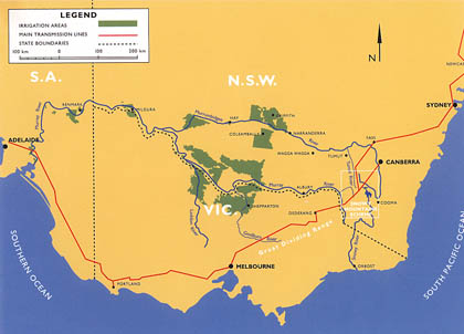
The Snowy Mountains Hydro-electric Scheme (SMHES) is
very large, covering 7 780 square kilometres. The original
purpose of the SMHES was to:
- collect,
regulate, and use the waters of the southward flowing
Snowy River and other streams in the Snowy Mountains
for generating large quantities of peak load electricity
for New South Wales, Victoria and the Australian Capital
Territory
- supplement
the westward flowing Murray and Murrumbidgee Rivers
to enable expansion by irrigation of primary production
on the dry but fertile plains of the Murray and Murrumbidgee
region.
The
Scheme operates entirely within the parameters of its
enabling legislation, the Snowy Mountains Hydro-electric
Power Act 1949 and the Schedule added in 1957.
(SMA, 1993: 8)
Building
the Scheme
A massive construction program, above and below the
ground, occupied workers for 25 years.
Australian
and overseas contractors built:
- 16
dams
- 7
power stations
- 145
kilometres of tunnels
- 80
kilometres of aqueducts
and
access roads were cut through the mountainous country.
There were many construction records set and broken
on the Scheme.
|
Bridges
Three types of bridge were built by the Snowy
Mountains Hydro-electric Authority (SMA):
- reinforced
concrete or steel girder
- Bailey,
timber or composite
- timber
span or suspension.
Most
bridges in use are concrete or steel girder. Bailey
bridges were originally designed as portable and
usually temporary bridges. One suspension footbridge
has been retained at Geehi Outlet.
|
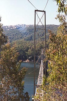
Suspension bridge (SMA,
1992) |
|
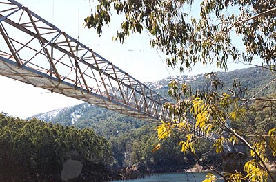
Suspension bridge (SMA, 1992)
|
Dams
Dams are perhaps the most prominent above ground civil
structures on the Scheme. There are sixteen dams spread
over the Scheme with a total storage capacity estimated
to be about thirteen times the volume of Sydney Harbour.
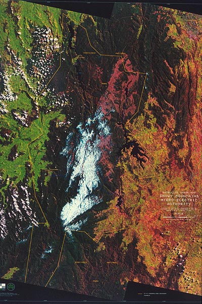
Satellite image of location of dams
(SMA, 1993: 9) |
Types
of dams
There are five principal types of dam, these terms refer
to the chief materials used in the construction of the
dam wall:
Dams on the Scheme
The most common type of dam on the Scheme is the concrete
gravity. Six dams are constructed in this way.
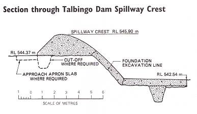
The
highest dam on the Scheme is Talbingo, a rockfill dam,
at 161 metres. The lowest is Khancoban, an earth- fill
dam, at 18 metres. Eucumbene Dam has the largest reservoir
capacity and Deep Creek the smallest.
Activity
Make labelled freehand sketches to explain the difference
between the types of dam.
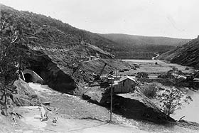
Eucumbene Dam
Lake Eucumbene is the largest reservoir in the Snowy
Mountains Scheme. It holds approximately nine times
the amount of water contained in Sydney Harbour and
covers more than 14 500 hectares. Lake Eucumbene collects
water from the Eucumbene, Upper Murrumbidgee and Snowy
Rivers and its enormous capacity is central to the flexibility
of the Scheme to generate electricity and provide irrigation
waters.
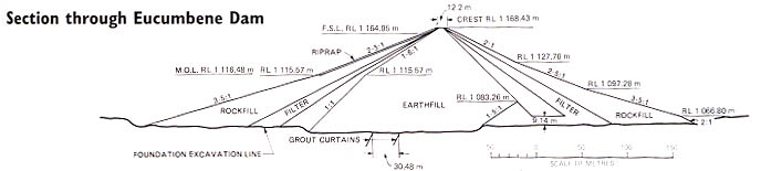
An
earthfill dam
Eucumbene Dam, one of only three earthfill dams on the
Scheme, holds the water of Lake Eucumbene. The other
earthfill dams are at Khancoban and Tooma. Eucumbene
Dam stands 116 metres high and is 686 metres thick at
its base. The outer walls of the dam are built of rock
while the inner core is compacted, impervious clay.
Eucumbene
Dam specifications
Type
Height
Crest length
Base width
Crest level |
Earthfill
116.1m
579.1m
686 m
RL 1 1683.43m |
Spillway
Type
Capacity
Crest length
Crest level
|
Overflow ski-jump and bucket with two vertical lift
gates, each 6.70m wide by 3.90m high
475 m3/s
13.4m
RL 1 161.30m |
|
Volume
of embankment
Earthfill
Filter
Rockfill
Total
|
3 810 800m
31 088 300m
31 836 200m
36 735 500m3
|
River
outlet works
|
0.15m
diameter bypass to provide Eucumbene Cove water
supply. Tunnel drainage valve modified for riparian
right releases of 0.07 m3/s.
|
| Foundation |
Closely
jointed hard siltstone and quartzite with overburden
of decomposed rock and slope-wash up to 6.10m deep. |
Other
features
|
Subsidiary
embankment containing 121 900 m3 of fill across
a low saddle in a ridge forming the left abutment. |
Reservoir
Gross Capacity
Active Capacity
Area at full supply level (FSL) |
4 798 400 x 103m3
4 366 500 x 103m3
14 500 ha |
Construction
period
|
May
1956 to May 1958 (the gated spillway was constructed
under a separate contract in 1977-78) |
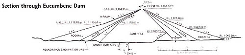
Section through Eucumbene Dam (SMA,
1993: 17) |
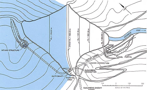 Plan
of Eucumbene Dam (SMA, 1993: 18)
Plan
of Eucumbene Dam (SMA, 1993: 18) |
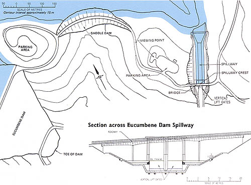
Plan of Eucumbene Dam Spillway (SMA,
1993: 18) |
Tunnels
Approximately 98% of the Scheme's engineering features
are underground. Tunnels and pipelines, dug deep under
the Snowy Mountains, measure 145 kilometres, and with
80 kilometres of aqueducts, collect and divert the inflows
of the Snowy Mountains area.
Overview
of tunnel features (shown in order of length)
| Tunnel |
Length
km |
Excavated
section
metres |
Lined
section
metres |
Percentage
lined |
Year
of completion |
Eucumbene-Snowy
Eucumbene-Tumut
Murrumbidgee-Eucumbene
Snowy-Geehi
Tooma-Tumut
Murray 1 Pressure
Tumut 2 Pressure and Tailwater
Jindabyne-Island Bend
Guthega
Murray 2 Pressure
Tumut 1 Pressure
Tumut 1 Tailwater |
23.5
22.2
16.6
14.5
14.3
11.8
11.3
9.8
4.7
2.4
2.4
1.3 |
6.30
x 6.35
6.91
3.35 x 3.35
6.30 x 6.30
3.79 x 3.71
-
-
3.96 x 3.96
5.87 x 5.74
-
-
8.53 x 7.77 |
6.10 x 6.10
6.40
3.10 x 3.10
6.10 x 6.10
3.43
6.93 x 6.93
6.40
3.76
5.26 x 5.05
7.47 x 7.47
6.40
7.93 x 7.49 |
19.7
28.3
17.7
13.3
20.0
100
100
10.6
11.6
100
100
54.5 |
1965
1959
1961
1966
1961
1966
1961
1968
1955
1969
1959
1959 |
Summary
of principal features (in SI Units) - tunnels (SMA,
1993: 172)

Specifications of Eucumbene-Tumut tunnel
(SMA, 1993: 25)
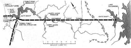
Plan of Eucumbene-Tumut tunnel (SMA,
1993: 25)
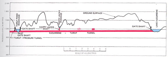
Profile of Eucumbene-Tumut tunnel (SMA,
1993: 25)
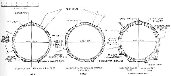
Tunnel cross-sections (SMA, 1993:
55)
Tunnelling
The longest tunnel is the Eucumbene-Snowy at 23.5 kilometres.
This tunnel diverts the water of the Snowy River from
Island Bend Pondage to storage in Lake Eucumbene, and
when required returns the water to the Snowy-Geehi Tunnel
at Island Bend. It took four years to build the tunnel,
a remarkable achievement when it is realised that the
geology of the Snowy Mountains is predominantly granite
and the diameter of the tunnel at maximum is 6.30 metres.
World
tunnelling records were established on the Scheme. In
1961, the Australian firm Thiess
Bros, were contracted for the Geehi section of the
Snowy-Geehi tunnel. In 1963, the firm established the
world record for hard rock tunnelling when 165 metres
of tunnel was formed in a week.
Swift
progress in tunnelling was the result of many factors,
but two deserve a special mention:
- the
sliding tunnel floor and
- rock
bolting.
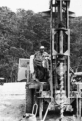
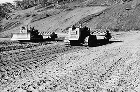
Sliding
tunnel floor
The sliding tunnel floor comprises a large sectionalised
steel working floor platform, which carried rail
tracks, points and crossings, drilling gantry and
other tunnelling equipment. A hydraulic jacking
system moves each of the three floor units forward
in six stages.
|
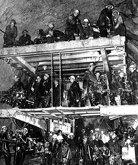
(Raymond, 1999) |
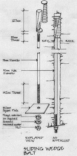
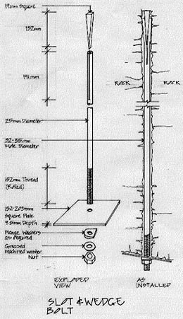
Rock
bolting
Rock bolts were used to support the roof and walls of
major structures such as tunnels and power stations.
Steel bolts, of different length and spacing, were inserted
into the rock where they were found to be an excellent
anchorage for the rock.
Rock
bolts were tension bolts, that when placed, compressed
broken or jointed rock surrounding the tunnel and converted
the rock into a self-supporting arch structure. The
technique of grouting, between the bolt and the rock,
was developed for upward sloping bolts. It is claimed
that the Snowy engineers developed the world's first
successful method of grouting the holes between rock
and bolt.
Activity
1. List a range of hardware items that can be used to
join masonry or support loads in rock. State the advantages
and disadvantages of each support mechanism.
2. Make labelled freehand sketches to illustrate how
these support mechanisms work.
|
Power
stations
The seven power stations (two of which are underground)
house the large generators and turbines that produce
the electricity from water that is stored in the
Scheme's ponds and reservoirs.
Power
from the Snowy Mountains Scheme is transmitted at 330kV
to the electricity systems of NSW, Victoria,
the ACT, SA and Queensland. The Scheme can generate 3 756 megawatts,
representing about 17% of the generating capacity
of South Eastern Australia.
|
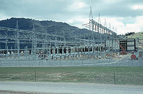
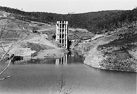
Lower
Tumut Switching Station at Talbingo in the final
stages of construction. Since 1973 this facility
has redistributed the power generated at nearby
Tumut 3 Power Station to Victoria and NSW along
330 000 volt transmission lines.
Photo: Bayram Ali
(Powerhouse Museum Collection) |
Towns
Towns like Eaglehawk, Sue City, Happy Jacks and Bella
Vista were purpose-built to service specific projects.
Home to hundreds or even thousands of people for several
years, they were dismantled after work was completed.
There were eight major townships.
| This
photograph depicts a street of houses for workers'
families at Eaglehawk near the Eucumbene Dam site
in winter in the mid-1950s. The town was built by
the NSW Public Works Department, which began the
Eucumbene Dam project. These buildings were prefabricated
in Sydney by Frank R. Wolstoneholme Pty Ltd and
transported to the Snowy by semi-trailer. Unfortunately
they were not specifically designed for use in the
freezing climate of the Snowy Mountains. External
water pipes froze in winter and the lack of insulation
and double-glazing added to the discomfort in cold
weather. |
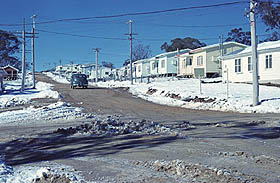
Photo:
Bayram Ali
(Powerhouse Museum Collection) |
|